

River Sand Dryer
Ⅰ Introduction
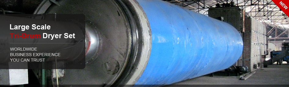
It’s widely used in fields of building materials, metallurgy, beneficiation, chemical industry, cement and so forth, to process such moister and heavier materials as slag, limestone, clay, river sand. The production line consists mainly of rotary drum, air induction devices, high speed thrashing devices, winnowing plates, auto-cleaning devices, actuating devices, conveying system, blast heaters, reducers, support and sealing systems. The complete plant features elegant design, perfect workmanship, stable performance, advanced technology, high yield, low energy consumption, small scale floor space and high level of mechanization.
Technical Parameters
| Model (m) | Handling capacity (t/h) | Motor power (kw) | Feedstock water content (%) | Coal heat value (kcal/kg) | Dried material water content (%) |
|---|---|---|---|---|---|
| GC-HSΦ1.5x14 | 10-12 | 15 | 20±3 | ≥5500 | ≤10 |
| GC-HSΦ1.8x14 | 15-18 | 18.5 | 20±3 | ≥5500 | ≤10 |
| GC-HSΦ2.0x16 | 20-25 | 18.5 | 20±3 | ≥5500 | ≤10 |
| GC-HSΦ2.2x18 | 25-30 | 22 | 20±3 | ≥5500 | ≤10 |
With outstanding handling capacity, this kind of dryer is also characteristic of high throughput, wide range of application, low flow resistance and convenient operation to process sand, river sand, slag, coal cinders, quartz sand and so on.
Process Flow Chart
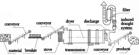
Basic working principles: through belt conveyer or bucket elevator to the hopper, the material will then be transported to the feed inlet via feeding pipes. Technically, the slant angle of the feeding pipe shall be larger than the material dip angle so as to the material can smoothly flow into the dryer. Within the drying drum, a horizontally oblique rotary cylinder, feedstock flowing into from the higher end of it will reversely contact with the heat-carrying agent from the lower end. There is also the design of concurrent flow of material and the agent flowing into the drum. The material will by gravity flow to the lower end while the drum is spinning. Going headway, the moist material will be dried either directly or indirectly by hot air and finally carried by the conveyer to the outlet. The shoveling plates upon the internal wall are for spreading material to the hot air so that the drying speed and efficiency can both be stepped up. Generally, the heat-carrying agent includes hot air, flue gas and the like. After drying work, material carried by the agent shall be separated through cyclone. For reducing dust content of the tail gas, bag type dust collector or hydrofilter shall be applied into use.
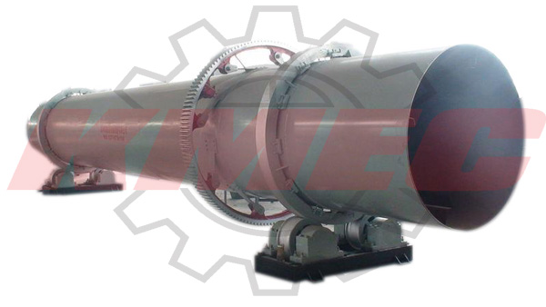
Ⅱ Main structure
1. drum 2. front roller 3. rear roller 4. gear 5. blocking roller 6. pulling roller 7. pinion 8. discharger 9. winnowing plates 10. reducer 11. motor 12. hot air duct 13. feeding chute 14. furnace body
As required, we can also offer gas producer, combustor, elevator, belt conveyer, dosing feeder, cyclone and induced fan.